Arduino LEGO robot
The idea of an Arduino controlled LEGO robot started by thinking about a cheap flexible robot platform which can be easyly adapted. After obtaining some inexpensive servos and a ATMEGA328P, I started thinking about how to create a flexible robot platform outoff these components. LEGO came to the rescue to make an easy adaptable platform.
Preparing the servo's
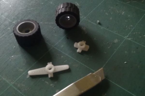 Wheels had to be added to the servo's. For this I used a small LEGO wheel.
A 4 mm hole was bored through the center of the wheel rim to be able to pass the fixing screw of the servo adapter.
I used the standard servo adapter supplied with the servo and cut it to size to fit into the wheel rim.
The adapter and wheel rim where glue together with 2-pack polyurethane glue.
Wheels had to be added to the servo's. For this I used a small LEGO wheel.
A 4 mm hole was bored through the center of the wheel rim to be able to pass the fixing screw of the servo adapter.
I used the standard servo adapter supplied with the servo and cut it to size to fit into the wheel rim.
The adapter and wheel rim where glue together with 2-pack polyurethane glue.
 In order to use the micro servos as continues rotating servo's the servo's had to be adapted.
There is a very good page on the conversion of the micro servo's at
todbot.com
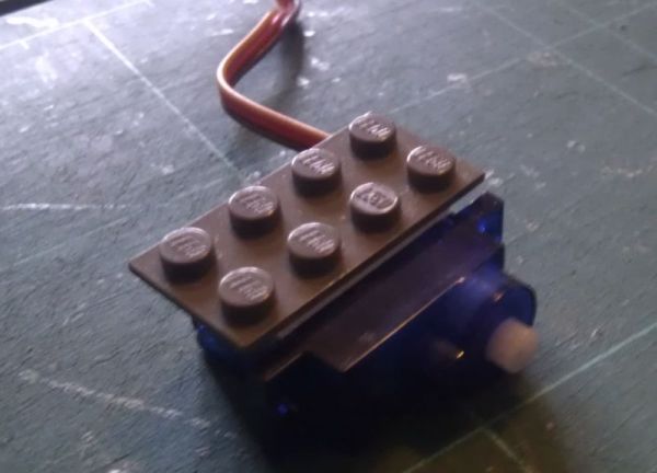
To be able to use the servo's in combination with LEGO parts I did stick a flattened 8 knob LEGO plate to
the servo using double sided tape. Flattening the lego parts can be easyly done by sticking sandpaper to a piece of plyboard.
Then rub the part over the sandpaper to flatten it.
Take care to allign the LEGO plates and the servo's properly.
This way the wheel axes will be alligned when both servo's are connected to a larger LEGO base plate.
In order to use the micro servos as continues rotating servo's the servo's had to be adapted.
There is a very good page on the conversion of the micro servo's at
todbot.com
To be able to use the servo's in combination with LEGO parts I did stick a flattened 8 knob LEGO plate to
the servo using double sided tape. Flattening the lego parts can be easyly done by sticking sandpaper to a piece of plyboard.
Then rub the part over the sandpaper to flatten it.
Take care to allign the LEGO plates and the servo's properly.
This way the wheel axes will be alligned when both servo's are connected to a larger LEGO base plate.
The Arduino version 1
 In order to create a compact robot platform I did not want to use the standard arduino uno that I used in another project.
So I purchased the ATMEGA328P chip with the arduino boot loader, a 16Mhz crystal and a Sparkfun FTDI basic USB to TTL serial convertor.
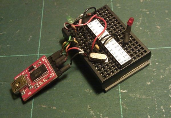
I used a mini breadboard to fit the components. The breadboard was fixed to a flat 24 knob LEGO plate using double sided tape.
In order to create a compact robot platform I did not want to use the standard arduino uno that I used in another project.
So I purchased the ATMEGA328P chip with the arduino boot loader, a 16Mhz crystal and a Sparkfun FTDI basic USB to TTL serial convertor.
I used a mini breadboard to fit the components. The breadboard was fixed to a flat 24 knob LEGO plate using double sided tape.
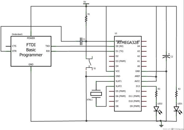 The Arduino was build on the breadboard as shown in the schematics.
All the smaller parts used like the LEDs, resistors and capacitors are parts salvaged from old electronic circuits and old kids toys.
The Arduino was build on the breadboard as shown in the schematics.
All the smaller parts used like the LEDs, resistors and capacitors are parts salvaged from old electronic circuits and old kids toys.
| Label | Part |
|---|---|
| C1 | 10nF Ceramic Capacitor |
| C2 | 1 uF Tantalum Capacitor |
| LED1, LED2 | Green LED - 3mm |
| Ond1 | FTDI Basic Programmer 5V |
| R1 | 10k Resistor |
| R2, R3 | 2.2k Resistor |
| S1 | Pushbutton |
| U1 | atmega328 |
| XTAL1 | 16 Mhz Crystal |
The robot
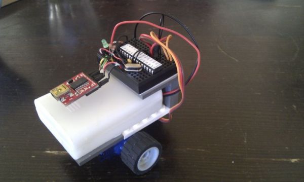 The robot was assembled using some additional LEGO components. The white box in the picture is the battery box salvaged outoff a toy.
It contains 3 non-recharchable AA batteries to supply the arduino and servos with 4,5 Volts power.
The battery box is attached with double sided tape to a 24 knob LEGO plate.
4 recharchable AAA batteries would also be a good alternative to supply 4.8 Volts of power to the arduino and servo's.
The robot was assembled using some additional LEGO components. The white box in the picture is the battery box salvaged outoff a toy.
It contains 3 non-recharchable AA batteries to supply the arduino and servos with 4,5 Volts power.
The battery box is attached with double sided tape to a 24 knob LEGO plate.
4 recharchable AAA batteries would also be a good alternative to supply 4.8 Volts of power to the arduino and servo's.
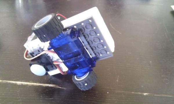 This picture shows how the servo's are attached to the base of the battery box.
In order for the robot to be able to rotate a LEGO glider brick is attached as a third 'wheel'.
The robot up till now did cost me around 30Euro for the servos, arduino chip, crystal, FTDI basic and breadboard.
Half of that was for the FTDI basic which can be removed and used for programming other projects.
This picture shows how the servo's are attached to the base of the battery box.
In order for the robot to be able to rotate a LEGO glider brick is attached as a third 'wheel'.
The robot up till now did cost me around 30Euro for the servos, arduino chip, crystal, FTDI basic and breadboard.
Half of that was for the FTDI basic which can be removed and used for programming other projects.
The arduino rev 2
 Version 2 is based on the same schematics as version 1.
The goal was to build the arduino in a very compact form factor.
Furthermore it should have the ability to add sensors for experimenting.
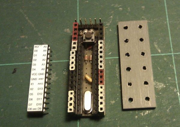
I came up with an arduino which does fit a 6x2 LEGO plate but which has still all the standard elements like a power led,
pin 13 led and reset button, as wel as a reset circuit for the FTDI.
Connections are made using enamelled copper wire for the I/O pins and connecting the components.
Thicker wire is used to create the + and - paths.
Version 2 is based on the same schematics as version 1.
The goal was to build the arduino in a very compact form factor.
Furthermore it should have the ability to add sensors for experimenting.
I came up with an arduino which does fit a 6x2 LEGO plate but which has still all the standard elements like a power led,
pin 13 led and reset button, as wel as a reset circuit for the FTDI.
Connections are made using enamelled copper wire for the I/O pins and connecting the components.
Thicker wire is used to create the + and - paths.
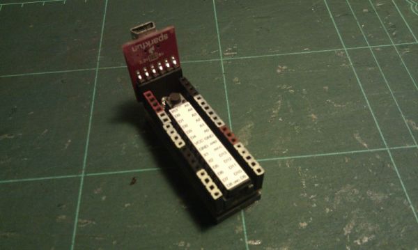 Shown in the picture is the finished arduino with the FTDI connected.
The white colored pins are the I/O pins. Red is +5V and black is ground.
This gives me enough connectivity to add sensors and add power for experiments.
Shown in the picture is the finished arduino with the FTDI connected.
The white colored pins are the I/O pins. Red is +5V and black is ground.
This gives me enough connectivity to add sensors and add power for experiments.
- www.schaalbouw.nl/projects © 2013 E.Paijmans
-

-

-
