H0 loc depot
For displaying and photographing the models I am creating in paper, I wanted to have an h0 railway module to put the models in a realistic setting. As a model builder I like to build a lot of stuff myself. It is fun to create something outoff nothing. This is also why I started builing paper models. The material is cheap, easy to handle and fun to work with.
My interrest in railways primairily focusses on old freight trains of the Dutch railways. I have choosen to build a small Dutch loc depot diorama which could be located near a branch line station around 1930.
Overview
Envision a small loc depot in 1930. Typically it contained all the elements to service small steam engines. Elements like water column, reservoir building (water tower), engine shed with work pit and a pit to remove the ash from the engine as wel as a coal supply is needed to service these steam engines. For displaying purposes I also included a period turntable and have choosen to recreate a small 13,5 meter turntable build with bricks as it was done frequently in the early railway period.
For operating the model railway I want to use techniques which are affordable and do support the 'build it yourself principle'. So no DCC controlled trains. However a little automation is nessecarry for the switch, the turntable and the locomotives The intension is to automate the module using an arduino microcontroller with a adafruit motor shield and a WII nunchuk but that will be disussed in later chapters of the build.
part 2 of the build.
Planning the layout
I started by determining the size of the layout. I ended up with an ideal size of 30 x 80 cm. This way it would be easy to transport, could sit on a regular shelf.
For an H0 layout however this is not very big. It was quite a puzzle to fit the above mentioned elements to service the steam engines and have trackwork without tight curves.
After quite some sketches I ended up with the layout as shown below.
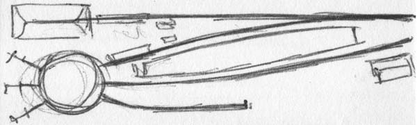
For more acurately planning the layout I had a look at the software available for creating a layout and ended up with Anyrail which is free for personal use up to 50 rail sections.
This resulted in the layout shown below. Note the potential fiddle yard to extend the posibilities of the layout.
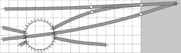 Note that the turntable is actually larger than the turnable on the actual layout. I was not able to find a
13,5 meter turntable in the Anyrail supplied rail libraries. The rail library used for the rails en switch is tillig.
Note that the turntable is actually larger than the turnable on the actual layout. I was not able to find a
13,5 meter turntable in the Anyrail supplied rail libraries. The rail library used for the rails en switch is tillig.
As a next step the actual module (30cm x 80cm) was build using one 120cm x 60cm sheet of 3 mm plywood. A box with a hight of 7,5 cm was created.
Enough to fit al the technical stuff.
The turntable pit
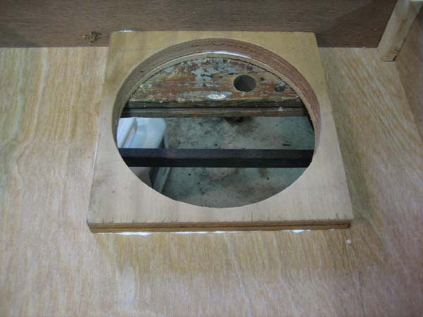 This first image shows the reenforcement at the place where the pit is made.
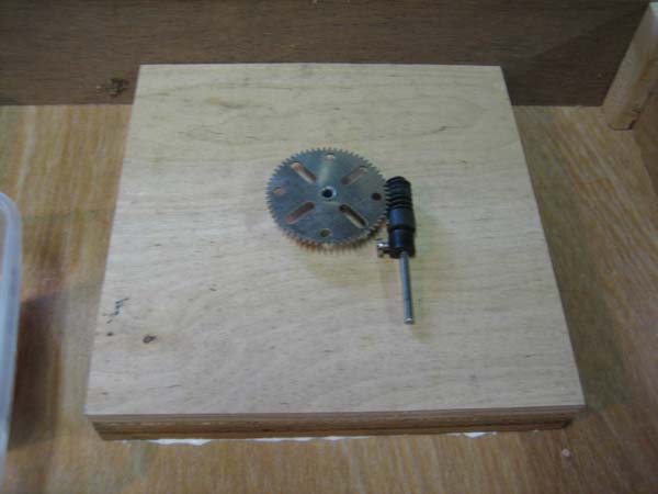
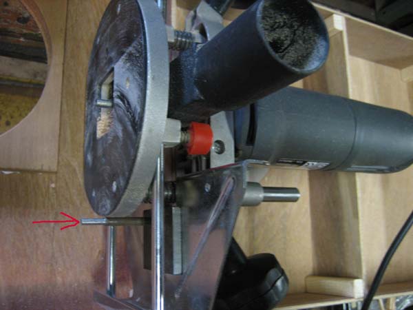 In this picture the router is shown with the pivot pin around which the router was turned.
 Underneath the turntable pit, a 6 mm bottom plate is mounted with 4 screws so it can be uncrewed to be able to work on the mechanism.
Also shown is the principle of the rotation with a gear and worm wheel. The worm wheel will be driven with a little stepper motor salvaged outoff a printer.
Underneath the turntable pit, a 6 mm bottom plate is mounted with 4 screws so it can be uncrewed to be able to work on the mechanism.
Also shown is the principle of the rotation with a gear and worm wheel. The worm wheel will be driven with a little stepper motor salvaged outoff a printer.
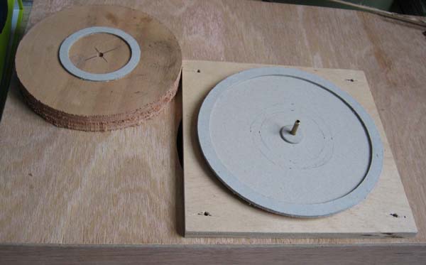 This picture shows the bottom of the pit with the cardboard rings (2 mm cardboard) to prepare the glueing of the pit bottom.
Also shown is the bit which will press the bottom of the pit down around the water drainage holes. Note the brass center pin.
When glueing it will ensure that the top and bottom part is centered as well as the bottom pit.
By using this technique the pit bottom will get a 2mm height difference towards the drainage holes.
This picture shows the bottom of the pit with the cardboard rings (2 mm cardboard) to prepare the glueing of the pit bottom.
Also shown is the bit which will press the bottom of the pit down around the water drainage holes. Note the brass center pin.
When glueing it will ensure that the top and bottom part is centered as well as the bottom pit.
By using this technique the pit bottom will get a 2mm height difference towards the drainage holes.
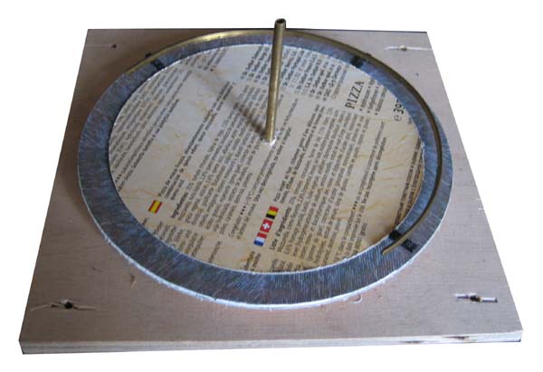 In this picture the textured bottom of the pit is glued in place. A cardboard ring is produced which will ease glueing the sleepers, holding the rail in place.
A section of rail is taken apart for the rail and sleepers. The sleepers were sawn to the correct length (12mm). The rail is bend into the radius as required. I used two halves which I soldered after finishing the glueing of the sleepers.
You can see a try fit of the rail with some sleepers.
In this picture the textured bottom of the pit is glued in place. A cardboard ring is produced which will ease glueing the sleepers, holding the rail in place.
A section of rail is taken apart for the rail and sleepers. The sleepers were sawn to the correct length (12mm). The rail is bend into the radius as required. I used two halves which I soldered after finishing the glueing of the sleepers.
You can see a try fit of the rail with some sleepers.
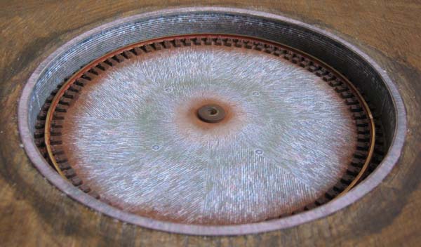
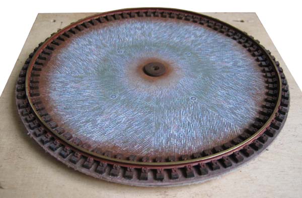 Here is the finished and wheatered pit bottom. The advantage of having a removable bottom is clear here. It is much easier to work on than trying to work on it when fixed.
In the center is the brass support for the center pin.
Here is the finished and wheatered pit bottom. The advantage of having a removable bottom is clear here. It is much easier to work on than trying to work on it when fixed.
In the center is the brass support for the center pin.
 The pit edges and top section is glued into place before attaching the bottom of the pit to the pit. In the picture the finished pit is show.
Below is the texture file which was used for building the turntable pit.

This work is licensed under a Creative Commons Attribution-NonCommercial-NoDerivs 3.0 Unported License
![]() Turntable pit H0
Turntable pit H0
- www.schaalbouw.nl/projects © 2013 E.Paijmans
-

-

-
