5 Inch gauge railway wagon CHD (part 3)
This section will describe the main parts of the chassis. The objective is building the chassis with easy to obtain materials but achieving an acceptable look.
Step 5 the chassis components.
 The chassis is build using square metal profiles. Easy to get at the local metal supplier.
The chassis however is build using u profiles. I used the bandsaw (in the vertical position)
to split the square profiles in half lenghtwise. With a course file I cleaned the cutting edge.
The profiles used were 30 x 30 mm for the headstock (to which the buffers are mounted). 25 x 25mm for the
solebars (long side members) and 15 x 15mm for the inside laying long steel sections and the cross-members
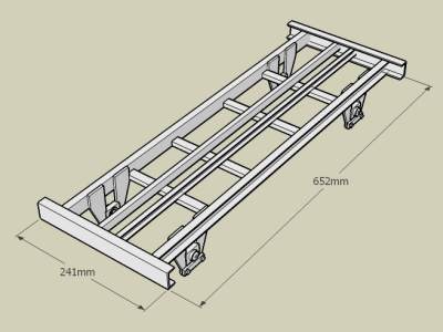
Based on the drawings the headstok was cut to a length of 241mm. The long side members to 651 mm.
The cross-members were not cut to length right now. The actual cut will be determined lateron based
on the actual measure of the wheelset from bearingblock to bearingblock.
After cutting al the structural sections of the chassis the solebars were first completed.
The chassis is build using square metal profiles. Easy to get at the local metal supplier.
The chassis however is build using u profiles. I used the bandsaw (in the vertical position)
to split the square profiles in half lenghtwise. With a course file I cleaned the cutting edge.
The profiles used were 30 x 30 mm for the headstock (to which the buffers are mounted). 25 x 25mm for the
solebars (long side members) and 15 x 15mm for the inside laying long steel sections and the cross-members
Based on the drawings the headstok was cut to a length of 241mm. The long side members to 651 mm.
The cross-members were not cut to length right now. The actual cut will be determined lateron based
on the actual measure of the wheelset from bearingblock to bearingblock.
After cutting al the structural sections of the chassis the solebars were first completed.
Step 6 The side members (solebars).
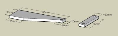 The wagon wheels are placed between legs. These legs are made outoff 4mm thick 30 mm flatbar. On the figure
on the left the strap is also shown. In the strap two 3 mm holes are bored to fix the straps to the legs lateron.
The wagon wheels are placed between legs. These legs are made outoff 4mm thick 30 mm flatbar. On the figure
on the left the strap is also shown. In the strap two 3 mm holes are bored to fix the straps to the legs lateron.
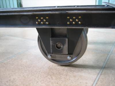 The legs should be atached to the solebars to be able to mount the bearingblock. A strap is attached to the bottom of the
legs to lock the bearingblock between the legs.
The legs should be atached to the solebars to be able to mount the bearingblock. A strap is attached to the bottom of the
legs to lock the bearingblock between the legs.
The legs are welded in place. In order to make sure the legs are properly spaced you can use two bearingblocks between the legs during the welding. In order to evenly space the brass rivets, a small template was made from flat stock. The template does fit between u section of the solebar. Using the template I drilled the 8 holes for the rivets which on the original chassis attach the legs to the solebar. The rivets are 1.8mm brass nails with round heads which can be found at he local hardware shop. When drilling 2mm holes the rivets fit easyly. I hammered the rivet flat at the back of the leg. During the hammering the rivet head is placed in a rivet cup.
At the end of the solebars 15 mm of the lowerpart of the u profile is removed to fit flat with the headstock
Step 7 Welding the chassis.
 Before welding the chassis together I bored the holes in the headstock for fitting the buffers, handles, steps and
coupling. Doing this afterwards would be difficult.
Before welding the chassis together I bored the holes in the headstock for fitting the buffers, handles, steps and
coupling. Doing this afterwards would be difficult.
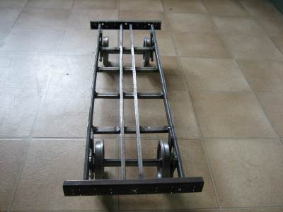
The chassis was welded together up-side-down. Notice that the bottom of the headstock should be flush with the bottom of the solebars, therefor the solebars and inner side-members should be on a plate which is at least 5 mm thick when welding up-side-down. Carefully align the solebars and headstock taking care that square angles are obtained and that the solebars and inner side members are properly spaced on the headstock. Take care that lateron the buffers can be mounted in thier proper position, so take care that the solebars do not overlap the buffer mounting holes. After welding the headstock to the sidemembers and solebars, place the cross-members between the solebars. Use clamps to fix them in thier final position. Then turn the chassis into its normal possition and weld the cross-members into place from the top of the chassis. This will give you a chassis looking like the picture on the left.
Back to CHD part 2 of the build. or to the next chapter CHD part 4 of the build.
- www.schaalbouw.nl/citroen © 2009 E.Paijmans
-

-

-
